
PicoLog 1000 Series
Precision You Can Trust
NABL-Accredited Calibration | Available on Request
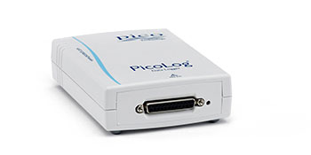
The PicoLog 1000 Series is a USB-powered multichannel voltage data logger and DAQ solution for sensor, transducer and general-purpose measurement applications. Available as the 12-channel PicoLog 1012 or 16-channel PicoLog 1216, the series offers 10- or 12-bit resolution, sampling up to 1 MS/s, digital outputs, optional terminal-board connectivity, PicoLog Cloud support and software tools for data logging and custom acquisition systems..
- Detail
- Special Features
- Specification
The PicoLog 1000 Series multichannel data logger is designed for engineers, laboratories, educational institutions, test departments and system developers who need to measure and record multiple voltage signals using a computer-based data acquisition system.
The series consists of two models:
- PicoLog 1012: 12 analog input channels with 10-bit resolution
- PicoLog 1216: 16 analog input channels with 12-bit resolution
Both devices provide a fixed 0 to +2.5 V single-ended input range, USB connectivity and multiple acquisition modes for applications ranging from long-duration data logging to faster transient capture.
Multichannel Voltage Data Acquisition
The PicoLog 1000 Series is designed primarily for general-purpose voltage, sensor and transducer logging.
Typical measurements can include signals from:
- Voltage-output sensors
- Pressure transducers
- Light sensors
- Position sensors
- Environmental sensors
- Industrial measurement circuits
- Laboratory experiments
- Electronic prototypes
- Process-monitoring systems
- Custom sensor interfaces
The PicoLog 1012 provides 12 analog inputs, while the PicoLog 1216 provides 16 analog inputs, allowing multiple measurement points to be monitored using one USB data logger.
Expandable Up to 320 Analog Channels
PicoLog software can operate with up to 20 Pico data loggers simultaneously.
Using twenty PicoLog 1216 units can therefore create a system with up to:
20 × 16 = 320 analog input channels
This expandable architecture is useful for applications where the required channel count may grow beyond the capability of one data logger.
Multiple Pico data-logging products can also be used within the same PicoLog software environment, making it possible to build larger or mixed measurement systems.
Flexible Sampling Modes
The PicoLog 1000 Series supports different acquisition modes depending on the required measurement speed and recording duration.
PicoLog Software Logging
Using PicoLog software, measurements can be recorded continuously at up to:
- 1 kS/s
The available recording duration is primarily limited by available computer storage rather than the logger's internal buffer.
This mode is suitable for applications such as:
- Environmental monitoring
- Process measurements
- Sensor characterization
- Long-duration experiments
- Battery testing
- Slow-changing electrical measurements
PicoSDK Streaming Mode
With PicoSDK streaming mode, the PicoLog 1000 Series supports sampling up to:
- 100 kS/s
This allows developers to build custom applications requiring faster continuous acquisition than standard PicoLog logging.
PicoScope / PicoSDK Block Mode
For faster acquisition, the logger supports sampling up to:
- 1 MS/s
This maximum rate is available through PicoScope or PicoSDK block-mode operation and applies under the conditions specified by Pico for high-speed acquisition.
The 1 MS/s capability makes the PicoLog 1000 Series useful for capturing shorter-duration signal events in addition to conventional long-term data logging.
Model-Specific Measurement Accuracy
The two PicoLog 1000 models provide different resolution and accuracy levels.
PicoLog 1012
- 12 analog inputs
- 10-bit resolution
- Accuracy: 1% of full scale
PicoLog 1216
- 16 analog inputs
- 12-bit resolution
- Accuracy: 0.5% of full scale
The PicoLog 1216 is therefore the better choice when additional channels and higher measurement resolution are required.
Fixed 0 to +2.5 V Input Range
Both models use a:
- 0 to +2.5 V input voltage range
- Single-ended input configuration
- Unipolar measurement architecture
- DC input coupling
- 1 MΩ input impedance
Because the standard input range is fixed, sensors producing signals outside this range require appropriate signal conditioning or scaling before connection.
Optional Terminal Board for Sensor Connections
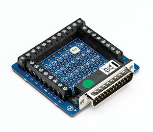
The PP545 Small Terminal Board is available for the PicoLog 1012 and PicoLog 1216.
It provides screw terminals that allow sensor wires to be connected without soldering. The board also includes locations where resistors can be installed to offset or extend the effective input measurement range.
This is useful for:
- Bare-wire sensor connections
- Prototype measurement systems
- Educational experiments
- Custom voltage-divider circuits
- Industrial sensor interfaces
- Permanent laboratory installations
The terminal board is optional unless purchased as part of a package that specifically includes it. Pico offers both logger-only and logger-with-terminal-board configurations.
Digital Outputs and Control Functions
The PicoLog 1000 Series also provides digital output capabilities.
PicoLog 1012:
- 2 digital outputs
PicoLog 1216:
- 4 digital outputs
- 1 PWM output
The digital outputs provide approximately:
- Logic low: 100 mV typical
- Logic high: 3.3 V
- Output protection: 1 kΩ series resistance
The PicoLog 1216 PWM output supports:
- Period: 100 µs to 1800 µs
- Duty cycle: 0% to 100%
- Adjustment: 1% steps
These outputs can be useful for simple control, triggering and experiment automation.
Sensor Power Output
The PicoLog 1000 Series provides a sensor power output rated at:
- 2.5 V
- 10 mA
- Current limited
This output may be used to power suitable low-power sensors or external circuitry within the manufacturer's specified limits.
PicoLog 6 Data Logging Software
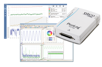
PicoLog 6 provides a graphical environment for configuring channels, recording measurements and viewing acquired data.
Functions include:
- Real-time data collection
- Channel configuration
- Data visualization
- Graph and table displays
- Calculated channels
- Alarm functionality
- Data export
- Multiple logger support
- Long-duration recording
The software is designed for both straightforward measurement setups and more complex multichannel acquisition systems.
PicoLog Cloud Support
The PicoLog 1000 Series currently supports PicoLog Cloud.
PicoLog Cloud allows compatible loggers to send capture data to Pico's cloud service and share measurement data using a link that can be opened in a browser on:
- PCs
- Phones
- Tablets
Pico also provides a cloud API that allows live capture data to be transferred into compatible third-party software or databases.
This can be useful for:
- Remote monitoring
- Distributed engineering teams
- Cloud-based test reporting
- Database integration
- Custom dashboards
- Remote experiment review
PicoSDK for Custom Applications
Pico provides an SDK and programming resources for developers who need to integrate the PicoLog 1000 Series into custom test or automation software.
The current programmer's guide identifies:
- PicoLog 1012: Part number PP543
- PicoLog 1216: Part number PP544
PicoSDK can be used for applications such as:
- Automated test systems
- Custom data acquisition software
- Production test equipment
- Research instrumentation
- Database-connected monitoring
- Laboratory automation
Typical Applications
The PicoLog 1000 Series is suitable for:
- General-purpose data acquisition
- Multichannel voltage logging
- Sensor and transducer monitoring
- Laboratory measurements
- Industrial process monitoring
- Educational experiments
- Electronic product development
- Research and development
- Environmental monitoring
- Automated test systems
- Production monitoring
- Long-duration data recording
- Prototype validation
- Custom DAQ systems
Up to 16 Analog Input Channels
The PicoLog 1000 Series provides:
- 12 channels on the PicoLog 1012
- 16 channels on the PicoLog 1216
This high channel count makes the series suitable for applications requiring multiple simultaneous sensor or voltage measurements.
Up to 12-Bit Resolution
The two models provide different ADC resolutions:
- PicoLog 1012: 10 bits
- PicoLog 1216: 12 bits
The PicoLog 1216 also offers higher published measurement accuracy at 0.5% of full scale, compared with 1% of full scale for the PicoLog 1012.
Up to 1 MS/s Sampling
The maximum acquisition rate is:
- 1 MS/s using PicoScope or PicoSDK block mode
Additional modes include:
- PicoLog: up to 1 kS/s
- PicoSDK streaming: up to 100 kS/s
This allows one device family to support both longer-duration logging and faster data acquisition applications.
Up to 320 Channels with Multiple Loggers
Up to 20 Pico data loggers can be connected to one computer using PicoLog software.
With twenty PicoLog 1216 devices, the system can provide up to 320 analog measurement channels.
70 kHz Analog Bandwidth
The PicoLog 1012 and 1216 have a published analog bandwidth of:
- DC to 70 kHz (-3 dB)
This specification is important when evaluating the logger for changing or higher-frequency voltage signals.
Optional PP545 Terminal Board
The PP545 Small Terminal Board provides:
- Screw-terminal sensor connections
- No-solder wiring
- Locations for range-extension resistors
- Direct connection to PicoLog 1012 and 1216
The terminal board can be purchased separately or included with specific product packages.
Digital Control Outputs
The series supports software-controllable digital outputs:
- PicoLog 1012: 2
- PicoLog 1216: 4
The PicoLog 1216 additionally includes a PWM output for simple control applications.
USB Powered Operation
The PicoLog 1000 Series receives power directly through its USB connection, eliminating the need for a separate external power supply during normal operation.
The PC interface is:
- USB 2.0 full speed
PicoLog Cloud
Current Pico software support includes PicoLog Cloud, enabling compatible captures to be uploaded and shared remotely through a browser-based link.
PicoSDK Support
Developers can control the data logger using PicoSDK, allowing the hardware to be integrated into:
- Custom applications
- Automated testing
- Production systems
- Database-connected measurement systems
- Research software
Compact and Lightweight Hardware
Both models have published physical dimensions of:
- 45 × 100 × 140 mm
Weight:
- Less than 200 g
Five-Year Warranty
Pico Technology currently specifies a:
- 5-year warranty
for the PicoLog 1000 Series.
Optional Traceable Calibration
Pico offers an optional voltage data logger calibration service with documented calibration information referenced to national standards.
This can be relevant for industrial, laboratory and scientific environments where measurement traceability is required.
Model Comparison
| Specification | PicoLog 1012 | PicoLog 1216 |
|---|---|---|
| Part Number | PP543 | PP544 |
| Analog Inputs | 12 | 16 |
| Resolution | 10 bits | 12 bits |
| Accuracy | 1% of full scale | 0.5% of full scale |
| Input Range | 0 to +2.5 V | 0 to +2.5 V |
| Analog Bandwidth (-3 dB) | DC to 70 kHz | DC to 70 kHz |
| Input Type | Single-ended, unipolar | Single-ended, unipolar |
| Input Coupling | DC | DC |
| Input Impedance | 1 MΩ | 1 MΩ |
| Overvoltage Protection | 30 V to ground | 30 V to ground |
| Maximum PicoScope Sample Rate | 1 MS/s | 1 MS/s |
| Maximum PicoLog Rate | 1 kS/s | 1 kS/s |
| Maximum PicoSDK Block Rate | 1 MS/s | 1 MS/s |
| Maximum PicoSDK Streaming Rate | 100 kS/s | 100 kS/s |
| Digital Outputs | 2 | 4 |
| PWM Output | No | 1 |
| Sensor Power Output | 2.5 V @ 10 mA | 2.5 V @ 10 mA |
| PC Interface | USB 2.0 | USB 2.0 |
| Power | USB powered | USB powered |
| I/O Connector | 25-way D female | 25-way D female |
| Terminal Board | Optional / available in bundled package | Optional / available in bundled package |
| Warranty | 5 years | 5 years |
Official model specifications:
Sampling and Memory Specifications
| Parameter | Specification |
| Maximum PicoScope Sampling | 1 MS/s |
| Maximum PicoLog Sampling | 1 kS/s |
| PicoSDK Block Mode | Up to 1 MS/s |
| PicoSDK Streaming | Up to 100 kS/s |
| Block Capture Memory at High Sample Rates | 8,000 samples |
| Capture Memory at Lower Sample Rates | Up to 1 million samples |
| PicoLog / Streaming Storage | Up to available PC storage |
Input Specifications
| Specification | Details |
| Input Type | Single-ended, unipolar |
| Voltage Range | 0 to +2.5 V |
| Input Coupling | DC |
| Input Impedance | 1 MΩ |
| Analog Bandwidth | DC to 70 kHz (-3 dB) |
| Overvoltage Protection | 30 V to ground |
| Resolution | 10 bits or 12 bits, model-dependent |
| Accuracy | 1% FS or 0.5% FS, model-dependent |
Output Specifications
| Specification | PicoLog 1012 | PicoLog 1216 |
| Digital Outputs | 2 | 4 |
| PWM Output | None | 1 |
| PWM Period | N/A | 100 µs to 1800 µs |
| PWM Duty Cycle | N/A | 0% to 100%, adjustable in 1% steps |
| Logic Low | 100 mV typical | 100 mV typical |
| Logic High | 3.3 V | 3.3 V |
| Output Current Limiting | 1 kΩ series resistors | 1 kΩ series resistors |
| Sensor Power | 2.5 V @ 10 mA | 2.5 V @ 10 mA |
Environmental Specifications
| Specification | Details |
| Specified Accuracy Temperature | 20 to 50 °C |
| Operating Temperature | 0 to 70 °C |
| Operating Humidity | 5 to 80% RH |
| Storage Temperature | -20 to +80 °C |
| Storage Humidity | 5 to 95% RH |
Physical Specifications
| Specification | Details |
| Dimensions | 45 × 100 × 140 mm |
| Weight | Less than 200 g |
| I/O Connector | 25-way D female |
| PC Interface | USB 2.0 full speed |
| Power Requirement | Powered from USB port |
| Ground Fault Protection | 0.9 A thermal self-resetting fuse |
Software and Operating-System Support
| Specification | Current Support |
| Data Logging Software | PicoLog |
| Oscilloscope Software | PicoScope |
| Programming Interface | PicoSDK |
| Cloud Logging | PicoLog Cloud |
| Windows | Windows 10 and 11, 64-bit |
| macOS | macOS 14 Sonoma or later, 64-bit |
| Linux | 64-bit Linux |
| USB Port Required | Yes |