
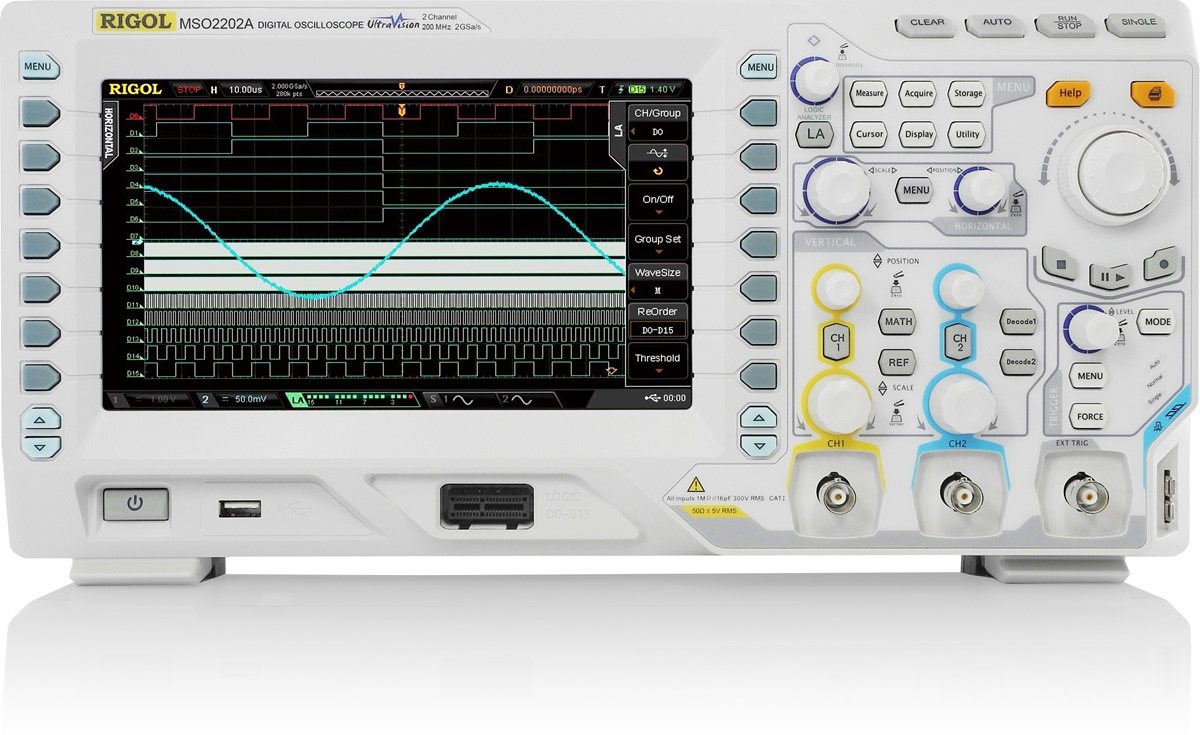
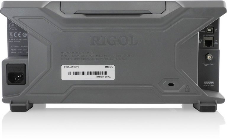
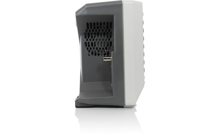
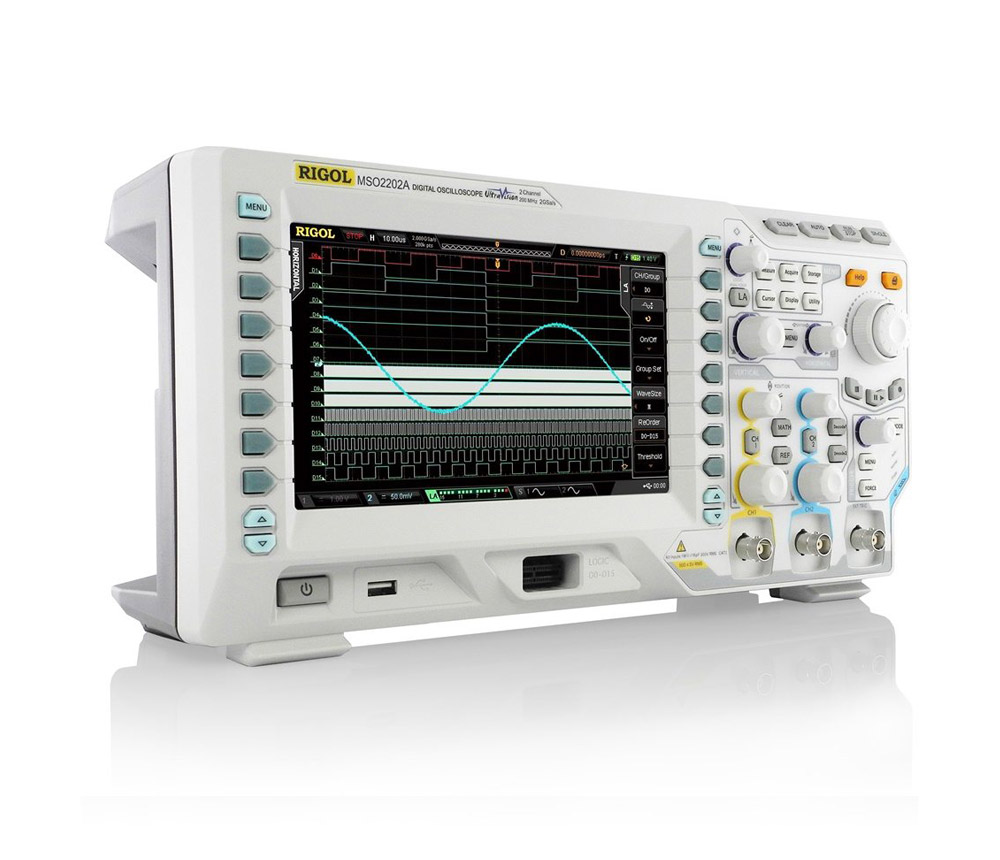
Rigol MSO2202A-S
Precision You Can Trust
NABL-Accredited Calibration | Available on Request
Rs. 158592.00
The RIGOL MSO2202A-S is a 200 MHz mixed-signal oscilloscope with two analogue channels, 16 digital channels and a built-in dual-channel 25 MHz function/arbitrary waveform generator. It offers up to 2 GSa/s analogue sampling, up to 1 GSa/s digital sampling, 14 Mpts standard analogue memory, waveform capture up to 52,000 wfms/s and hardware recording for advanced embedded-system, electronics and production testing..
The RIGOL MSO2202A-S Mixed-Signal Oscilloscope combines oscilloscope, logic-analysis and waveform-generation capabilities in one benchtop instrument. It is designed for engineers, technicians, research laboratories, electronics manufacturers and educational institutions that need to generate test signals while observing analogue and digital circuit behaviour.
The instrument provides:
- Two analogue oscilloscope channels
- 200 MHz analogue bandwidth
- Sixteen digital logic channels
- Two waveform-generator output channels
- Up to 2 GSa/s analogue sampling
- Up to 1 GSa/s digital sampling
- Deep analogue and digital acquisition memory
- Protocol triggering and decoding
- Hardware waveform recording
- FFT and waveform mathematics
- An 8-inch colour display
The integrated signal source distinguishes the MSO2202A-S from the standard MSO2202A. Engineers can generate a stimulus signal, apply it to a circuit and monitor the resulting analogue and digital behaviour without connecting a separate function generator.
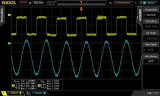
200 MHz Analogue Bandwidth
The MSO2202A-S provides 200 MHz bandwidth across two analogue input channels. Its calculated rise time is approximately 1.8 ns, making it suitable for embedded controllers, digital interfaces, switching circuits and general electronics development.
Typical measurements include:
- Microcontroller clock signals
- FPGA and CPLD outputs
- PWM and pulse waveforms
- Switching power-supply control signals
- Sensor and actuator outputs
- Analogue amplifier signals
- Communication interface waveforms
- Timing and phase relationships
- Input and output waveform comparison
- General signal-integrity troubleshooting
The oscilloscope provides selectable 1 MΩ and 50 Ω input impedance, allowing engineers to work with general high-impedance measurements and correctly terminated higher-frequency signals.
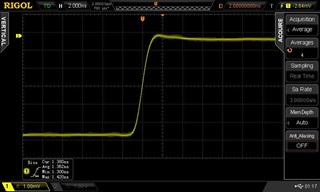
Two Analogue and 16 Digital Channels
The mixed-signal architecture combines analogue waveform measurement with digital logic analysis.
The MSO2202A-S supports:
- Two analogue input channels
- Sixteen digital channels through a compatible RPL2316 logic probe
- Time-correlated analogue and digital display
- Triggering from analogue or digital sources
- Digital channel grouping and labelling
- Parallel bus analysis
- Configurable digital logic thresholds
This configuration is useful for analysing:
- Analogue sensor signals and digital controller responses
- Clock, data and enable relationships
- Microcontroller GPIO activity
- FPGA timing
- Parallel buses
- Power-rail behaviour during logic switching
- Communication signals and electrical waveform quality
- Mixed analogue and digital fault conditions
The digital inputs are arranged in two groups of eight channels. Each group can use a separate logic threshold.
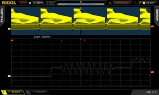
Analogue Sampling Performance
The analogue acquisition system provides:
- Up to 2 GSa/s with one analogue channel active
- Up to 1 GSa/s per channel with both analogue channels active
The peak-detect function can capture narrow pulses of approximately:
- 500 ps in single-channel operation
- 1 ns in dual-channel operation
The high sampling rate helps reveal waveform details such as overshoot, ringing, short glitches, timing variation and pulse distortion.
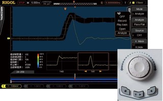
Digital Sampling Performance
The digital sample rate depends on the number of enabled logic channels:
- Up to 1 GSa/s with eight digital channels active
- Up to 500 MSa/s with all 16 digital channels active
Digital peak-detection performance is approximately:
- 1 ns with eight channels
- 2 ns with 16 channels
The minimum detectable digital pulse width is approximately 5 ns.
The 2 GSa/s value applies to the analogue acquisition system. The digital logic channels provide a maximum sample rate of 1 GSa/s.
Deep Analogue Acquisition Memory
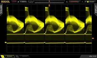
The oscilloscope provides 14 Mpts standard analogue memory in single-channel operation.
Standard analogue memory allocation:
- 14 Mpts with one analogue channel
- 7 Mpts per channel with two analogue channels
The optional memory upgrade increases acquisition depth to:
- 56 Mpts with one analogue channel
- 28 Mpts per channel with two analogue channels
Deep memory allows longer waveform captures while retaining a useful sample rate. It is beneficial for:
- Serial communication analysis
- Long pulse trains
- Converter start-up testing
- Embedded timing sequences
- PWM analysis
- Communication packet testing
- Intermittent fault investigation
- Production monitoring
The 56 Mpts memory depth must be listed as optional unless the appropriate memory licence is installed.
Digital Acquisition Memory
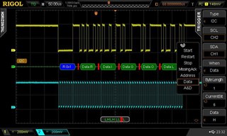
Digital memory is allocated according to the number of active digital channels.
Standard digital memory:
- 14 Mpts with up to eight digital channels
- 7 Mpts with all 16 digital channels
Optional digital memory:
- 28 Mpts with up to eight digital channels
- 14 Mpts with all 16 digital channels
This supports longer logic captures during parallel bus testing, FPGA debugging and embedded-system timing analysis.
Built-In Dual-Channel 25 MHz Signal Source
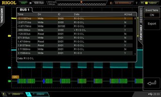
The MSO2202A-S includes a two-channel function and arbitrary waveform generator as standard.
It can generate common test signals such as:
- Sine
- Square
- Ramp
- Pulse
- Noise
- DC
- Built-in arbitrary waveforms
- User-defined arbitrary waveforms
The integrated signal source is useful for:
- Amplifier testing
- Filter evaluation
- Circuit-response analysis
- Sensor simulation
- Clock and pulse generation
- Component testing
- Educational experiments
- Stimulus-response measurements
- Embedded-system development
Both waveform-generator channels can be configured independently, allowing engineers to generate two related or separate test signals.
Modulation, Sweep and Burst Functions
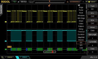
The signal source supports advanced generation modes for circuit testing.
Available functions include:
- Amplitude modulation
- Frequency modulation
- Frequency-shift keying
- Frequency sweep
- Burst output
- Phase adjustment
- Output impedance selection
These functions support testing of communication circuits, filters, amplifiers, modulation systems and triggered electronic devices.
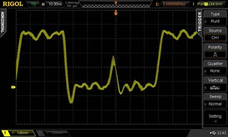
Arbitrary Waveform Generation
The integrated generator allows users to create and output custom waveforms.
Arbitrary waveform capability is useful when a circuit must be tested with:
- Non-standard pulse shapes
- Simulated sensor signals
- Recorded waveform patterns
- Repetitive transient signals
- Custom control waveforms
- Application-specific test signals
The oscilloscope interface allows arbitrary waveform points to be edited and stored for later use.
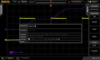
Fast Waveform Capture
The MSO2202A-S provides waveform capture rates up to 52,000 waveforms per second under the specified operating configuration.
Fast acquisition improves the probability of detecting:
- Short glitches
- Runt pulses
- Timing violations
- Signal dropouts
- Intermittent noise
- Unstable waveform edges
- Abnormal pulse widths
- Communication errors
The display uses up to 256 intensity levels to distinguish frequently occurring waveform activity from rare events.
Hardware Waveform Recording
The instrument supports hardware recording, playback and analysis.
Maximum recording capacity includes:
- Up to 65,000 frames with digital channels disabled
- Up to 32,000 frames with digital channels enabled
Waveform recording allows engineers to:
- Capture successive signal events
- Replay waveform activity
- Review individual frames
- Compare normal and abnormal behaviour
- Perform post-acquisition measurements
- Investigate intermittent faults
- Examine the sequence preceding a failure
Low-Level Analogue Measurements
The analogue inputs support vertical sensitivity from:
- 500 µV/div to 10 V/div at 1 MΩ
- 500 µV/div to 1 V/div at 50 Ω
This range is suitable for:
- Sensor output measurement
- Power-supply ripple analysis
- Amplifier testing
- Reference-voltage checks
- Small analogue signals
- General electronics troubleshooting
The 500 µV/div setting uses digital amplification based on the 1 mV/div range and should be considered during precision measurements.
Selectable Bandwidth Limits
Users can select:
- 20 MHz
- 100 MHz
- Full 200 MHz bandwidth
Bandwidth limiting helps suppress unwanted high-frequency noise when the signal under test occupies a lower frequency range.
Digital Logic Thresholds
The digital channels support predefined and user-configurable thresholds for common logic standards.
Supported threshold types include:
- TTL
- 5 V CMOS
- 3.3 V CMOS
- 2.5 V CMOS
- 1.8 V CMOS
- ECL
- PECL
- LVDS
- 0 V
- User-defined threshold
The user-defined threshold range is approximately ±20 V with 10 mV adjustment resolution.
Trigger Functions
The MSO2202A-S provides several trigger modes for isolating specific analogue and digital conditions.
Standard trigger functions include:
- Edge
- Pulse width
- Slope
- Pattern
- Runt
- Setup and hold
- Video
- RS232/UART
- I2C
- SPI
Optional trigger functions include:
- Window
- Nth edge
- HDTV
- Delay
- Timeout
- Duration
- USB
- CAN
Optional trigger functions require the corresponding software licence.
Serial and Parallel Bus Analysis
The instrument supports bus triggering and decoding across analogue and digital channels.
Available bus analysis includes:
- Parallel bus
- RS232/UART
- I2C
- SPI
- CAN
Protocol analysis allows users to:
- View decoded data values
- Trigger on selected communication events
- Correlate protocol data with electrical waveforms
- Identify timing errors
- Find missing acknowledgements
- Locate corrupted packets
- Investigate physical-layer faults
Parallel bus analysis is available as part of the mixed-signal functionality. Serial decoding and CAN analysis may require applicable licences.
Automatic Measurements
The oscilloscope provides automatic measurements for common voltage, timing, pulse and frequency parameters.
Analogue measurements include:
- Maximum and minimum voltage
- Peak-to-peak voltage
- Amplitude
- Average voltage
- RMS voltage
- Frequency and period
- Rise and fall time
- Positive and negative pulse width
- Duty cycle
- Overshoot and preshoot
- Phase
- Delay
- Area and period area
Digital measurements include:
- Frequency
- Period
- Pulse width
- Duty cycle
- Phase
- Delay
Measurement statistics can show the current, average, maximum, minimum and standard deviation values.
FFT and Waveform Mathematics
Built-in waveform-analysis functions include:
- Addition
- Subtraction
- Multiplication
- Division
- FFT
- Digital filtering
- Logic operations
- Integration
- Differentiation
- Logarithmic functions
- Exponential functions
- Square root
- Trigonometric functions
FFT analysis is useful for harmonic measurement, switching-frequency evaluation, clock-spectrum observation, noise analysis and EMI troubleshooting.
Pass/Fail Testing
Mask-based pass/fail testing compares acquired waveforms with user-defined tolerance limits.
It can support:
- Production testing
- Repetitive quality checks
- Component comparison
- Signal-stability monitoring
- Detection of waveform deviations
- Automated validation
The AUX output can provide a trigger or pass/fail signal to external equipment.
Applications
The RIGOL MSO2202A-S is suitable for:
- Embedded-system development
- Microcontroller debugging
- FPGA and CPLD testing
- Mixed-signal circuit analysis
- Digital logic debugging
- Function-generator applications
- Amplifier and filter testing
- Sensor simulation
- Parallel bus analysis
- Serial protocol testing
- Power-supply analysis
- PWM testing
- Production-line validation
- Research and development
- Engineering education
- Electronic service and repair
Why Buy from RevineTech?
RevineTech supplies test and measurement instruments for electronics development, industrial testing, research, production and education.
Technical selection assistance can cover:
- MSO2202A-S configuration
- Analogue and digital memory upgrades
- Serial protocol licences
- CAN analysis software
- Advanced trigger options
- Logic-probe requirements
- Passive and differential probes
- High-voltage and current probes
- Calibration requirements
- Automated test integration